
CTLB Hydraulic High-Pressure Swing Clamp
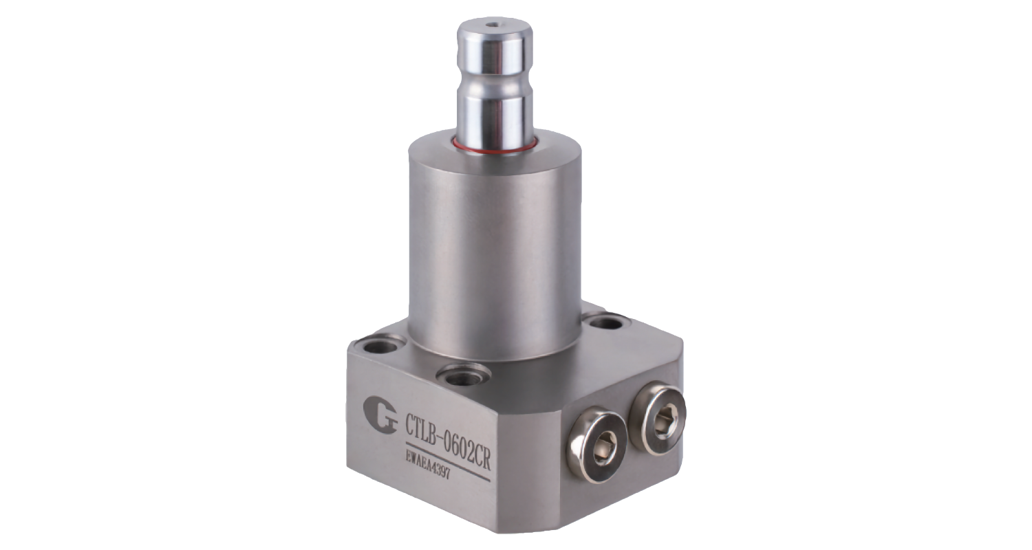
Hydraulic High-Pressure Swing Clamp – compact design and high clamping forces
- Compact hydraulic swing clamp for automated clamping fixtures and machining applications
- Robust design for hydraulic pressures up to 350 bar
- Swing and clamping movement enables fast and space-saving workpiece loading
- Seven sizes from CTLB-0402 to CTLB-4002
- Clamping forces up to approx. 43.3 kN, depending on size, hydraulic pressure and clamping arm length
- Max. operating pressure: 350 bar
- Min. operating pressure: 7 bar
- Total stroke from 14 to 35.5 mm, depending on size
- Operating temperature: 0 to +70 °C
- Optional connection for speed control
- The actual clamping force depends on the hydraulic pressure and the length of the clamping arm used.
- The clamping and unclamping movement should not be operated at excessive speed.
- For precise adjustment of the clamping speed, the use of an oil flow control valve is recommended.
- The required mounting and fastening elements are not included in the scope of delivery.
- Right-hand or left-hand swing direction available.
- Other versions and customized solutions available on request.
- CAD data is available in the “CAD & Downloads” section.
CTLB-0402CR
| ① | CTLB | Series | CTLB – Hydraulic high-pressure swing clamp |
|---|---|---|---|
| ② | 0402 | Size | 0402 : Cylinder Ø 32 mm 0602 : Cylinder Ø 36 mm 0802 : Cylinder Ø 39 mm 1002 : Cylinder Ø 46 mm 1602 : Cylinder Ø 53 mm 2502 : Cylinder Ø 71 mm 4002 : Cylinder Ø 90 mm |
| ③ | C | Connection type | C : O-ring connection with G-thread plug |
| ④ | R | Swing direction | R : Right L : Left |
Technical Data – CTLB Hydraulic High-Pressure Swing Clamp
| Size | Clamping Force at 350 bar | Clamping Stroke | Swing Stroke | Total Stroke | Oil Volume Clamping | Oil Volume Unclamping | Effective Piston Area Clamping | Effective Piston Area Unclamping |
|---|---|---|---|---|---|---|---|---|
| [kN] | [mm] | [mm] | [mm] | [cm³] | [cm³] | [cm²] | [cm²] | |
| CTLB-0402 | 3,50 | 6 | 8 | 14 | 3,6 | 1,4 | 2,545 | 1,005 |
| CTLB-0602 | 5,08 | 7 | 8 | 15 | 5,2 | 2,2 | 3,463 | 1,453 |
| CTLB-0802 | 6,90 | 8 | 10 | 18 | 8,1 | 3,6 | 4,524 | 1,979 |
| CTLB-1002 | 9,80 | 9,5 | 10 | 19,5 | 12,9 | 5,5 | 6,605 | 2,804 |
| CTLB-1602 | 14,90 | 11 | 13 | 24 | 21,8 | 10,0 | 9,079 | 4,170 |
| CTLB-2502 | 28,69 | 16 | 16 | 32 | 57,9 | 26,2 | 18,096 | 8,198 |
| CTLB-4002 | 43,29 | 19,5 | 16 | 35,5 | 100,4 | 43,9 | 28,274 | 12,370 |
Note: The achievable clamping force depends on the hydraulic pressure and the length of the clamping arm used. For precise sizing, refer to the corresponding clamping force diagrams.
Technical Drawing
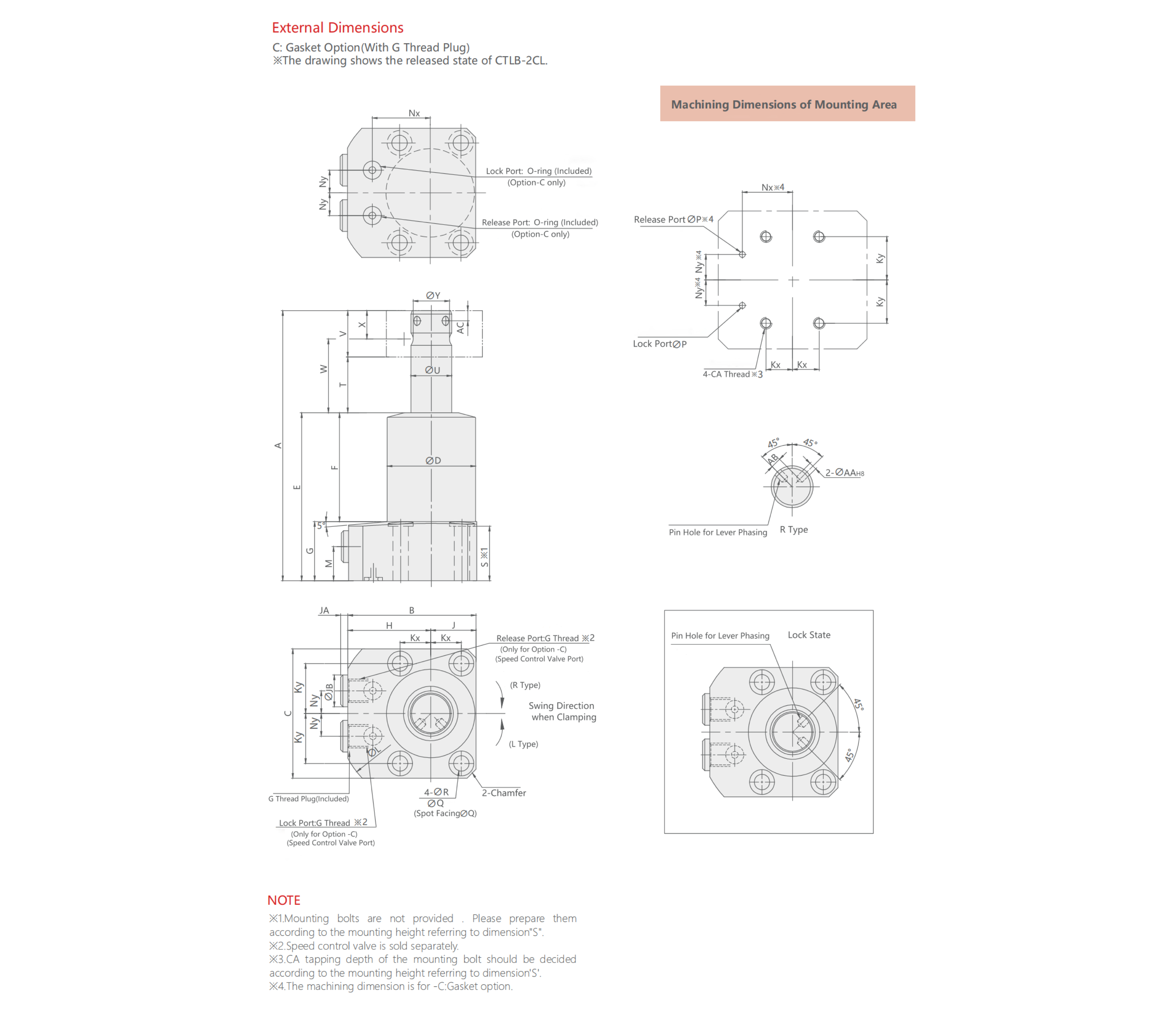
| Size | Total Stroke | Clamping Stroke | Swing Stroke | A | B | C | D | E | F | G | H | J | Kx | Ky | L | M | Nx | Ny | P | Q | R | S | T | U | V | W | X | Y | AA | AB | AC | CA (Nom. X Pitch) | JA | JB | Chamfer | G Thread | O-Ring (Option C) | Lever Pin (Included) |
|---|---|---|---|---|---|---|---|---|---|---|---|---|---|---|---|---|---|---|---|---|---|---|---|---|---|---|---|---|---|---|---|---|---|---|---|---|---|---|
| CTLB-0402 | 14 | 6 | 8 | 97.5 | 49.5 | 47 | 32 | 62.5 | 36.5 | 26 | 33 | 16.5 | 11 | 18 | 76 | 15 | 22 | 9 | 3 | 9 | 5.5 | 24 | 16 | 14 | 19 | 25.5 | 9.5 | 12.5 | 3 +0.014⁄0 | 4 | 3.5 | M5X0.8 | 4 | 14 | 3 | G1/8 | 1BP5 | Φ3×6 |
| CTLB-0602 | 15 | 7 | 8 | 105 | 53.5 | 55 | 36 | 66 | 40 | 26 | 35 | 18.5 | 12 | 21 | 78 | 15 | 24 | 9 | 3 | 11 | 6.8 | 24 | 17 | 16 | 22 | 28 | 11 | 14 | 4 +0.018⁄0 | 4 | 4.5 | M6 | 4 | 14 | 4 | G1/8 | 1BP5 | Φ4×8 |
| CTLB-0802 | 18 | 8 | 10 | 119 | 56.5 | 57 | 39 | 74 | 48 | 26 | 36.5 | 20 | 13.5 | 22 | 83 | 15 | 25.5 | 10 | 3 | 11 | 6.8 | 24 | 20 | 18 | 25 | 32.5 | 12.5 | 16 | 4 +0.018⁄0 | 5 | 4.5 | M6 | 4 | 14 | 4 | G1/8 | 1BP5 | Φ4×8 |
| CTLB-1002 | 19.5 | 9.5 | 10 | 134.5 | 64 | 70 | 46.5 | 83 | 57 | 26 | 40 | 24 | 16 | 27 | 93 | 15 | 29 | 12 | 3 | 14 | 9 | 24 | 21.5 | 22 | 30 | 36.5 | 15 | 19.5 | 4 +0.018⁄0 | 7 | 4.5 | M8 | 4 | 14 | 4 | G1/8 | 1BP5 | Φ4×8 |
| CTLB-1602 | 24 | 11 | 13 | 159.5 | 71.5 | 71 | 53 | 99.5 | 72.5 | 27 | 43.5 | 28 | 20 | 27.5 | 98 | 16 | 32.5 | 14 | 3 | 14 | 9 | 25 | 26 | 25 | 34 | 43 | 17 | 22 | 4 +0.018⁄0 | 8.5 | 5 | M8 | 4 | 14 | 4 | G1/8 | 1BP5 | Φ4×8 |
| CTLB-2502 | 32 | 16 | 16 | 211 | 99.5 | 84 | 71 | 131 | 101 | 30 | 57.5 | 42 | 32 | 32 | 132 | 16.5 | 43.5 | 19 | 5 | 17.5 | 11 | 28 | 34 | 35.5 | 46 | 57 | 23 | 31 | 6 +0.018⁄0 | 11.75 | 6.5 | M10 | 4.5 | 19 | 6 | G1/4 | 1BP7 | Φ6×12 |
| CTLB-4002 | 35.5 | 19.5 | 16 | 241 | 118 | 102 | 90 | 148.5 | 112.5 | 36 | 67 | 51 | 40 | 40 | 148 | 22.5 | 53 | 20 | 5 | 20 | 14 | 33 | 37.5 | 45 | 55 | 65 | 27.5 | 39.5 | 8 +0.018⁄0 | 14.5 | 9 | M12 | 4.5 | 19 | 6 | G1/4 | 1BP7 | Φ8×16 |
Clamping Force Depending on Hydraulic Pressure and Clamping Arm Length
The achievable clamping force of the CTLB swing clamp depends on the applied hydraulic pressure and the length of the clamping arm used. The following clamping force diagrams provide guidance for selecting and sizing the swing clamp for the respective application.
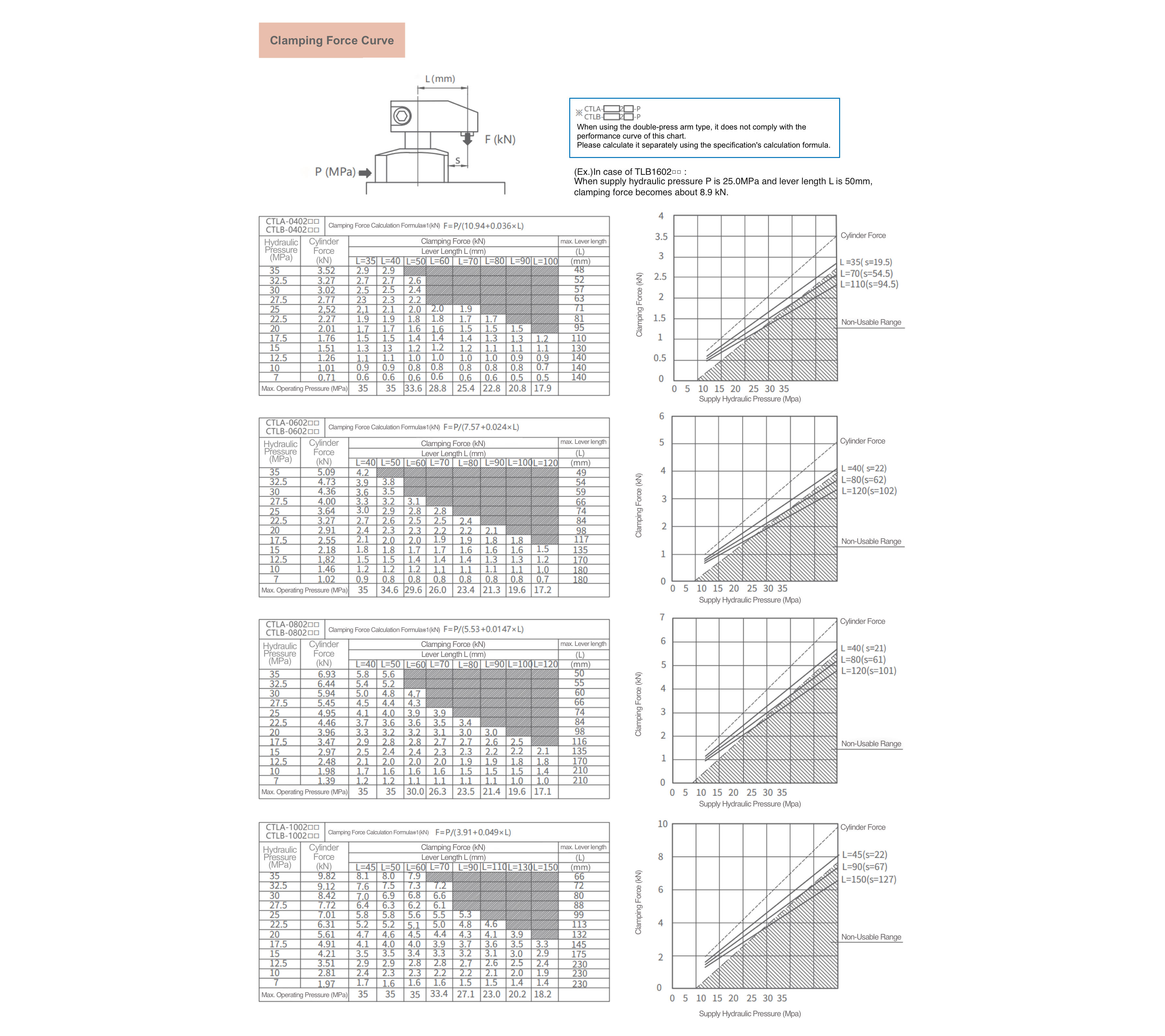
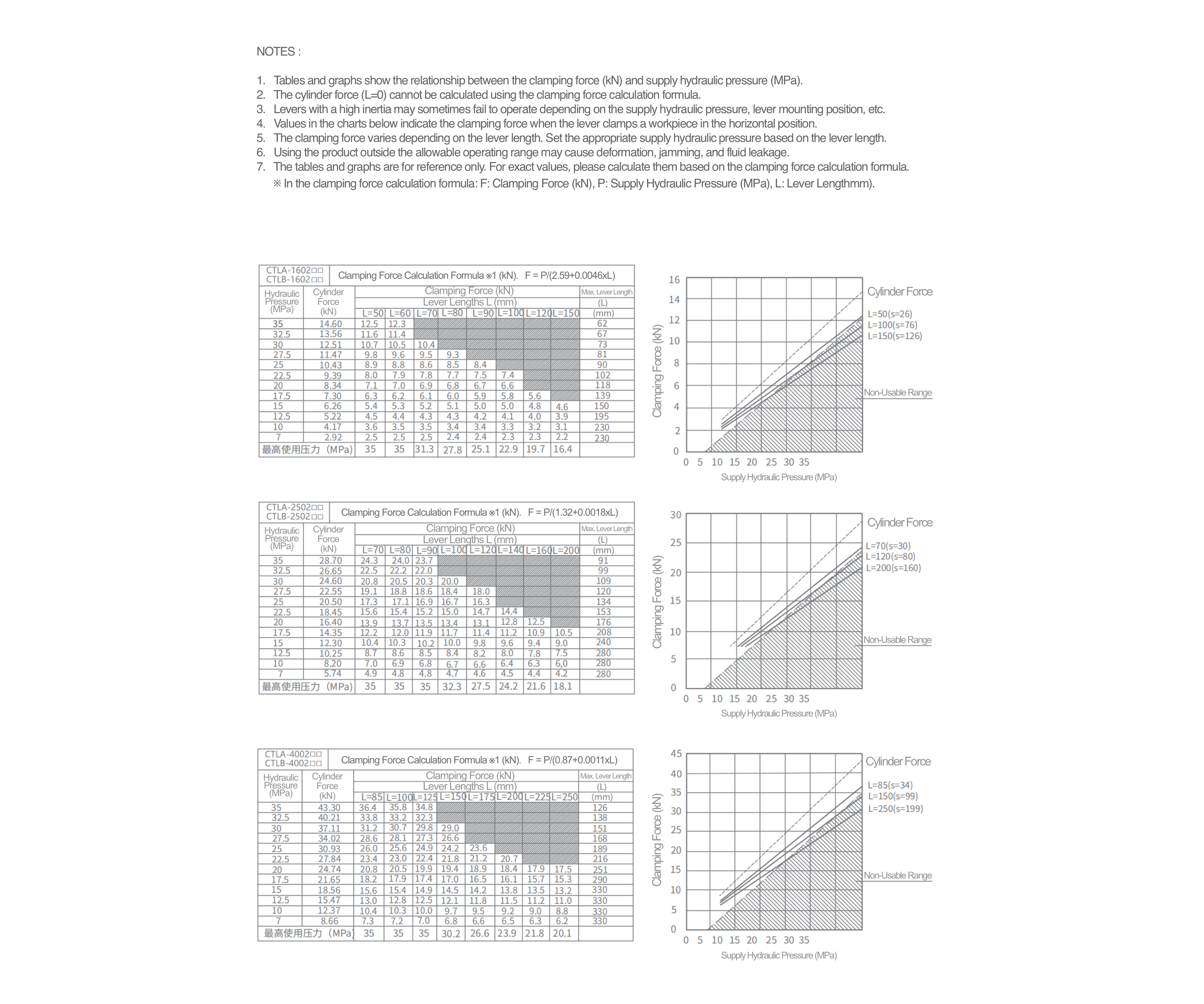
When selecting the swing clamp, both the required clamping force and the permissible clamping arm length and maximum operating pressure must be taken into account.
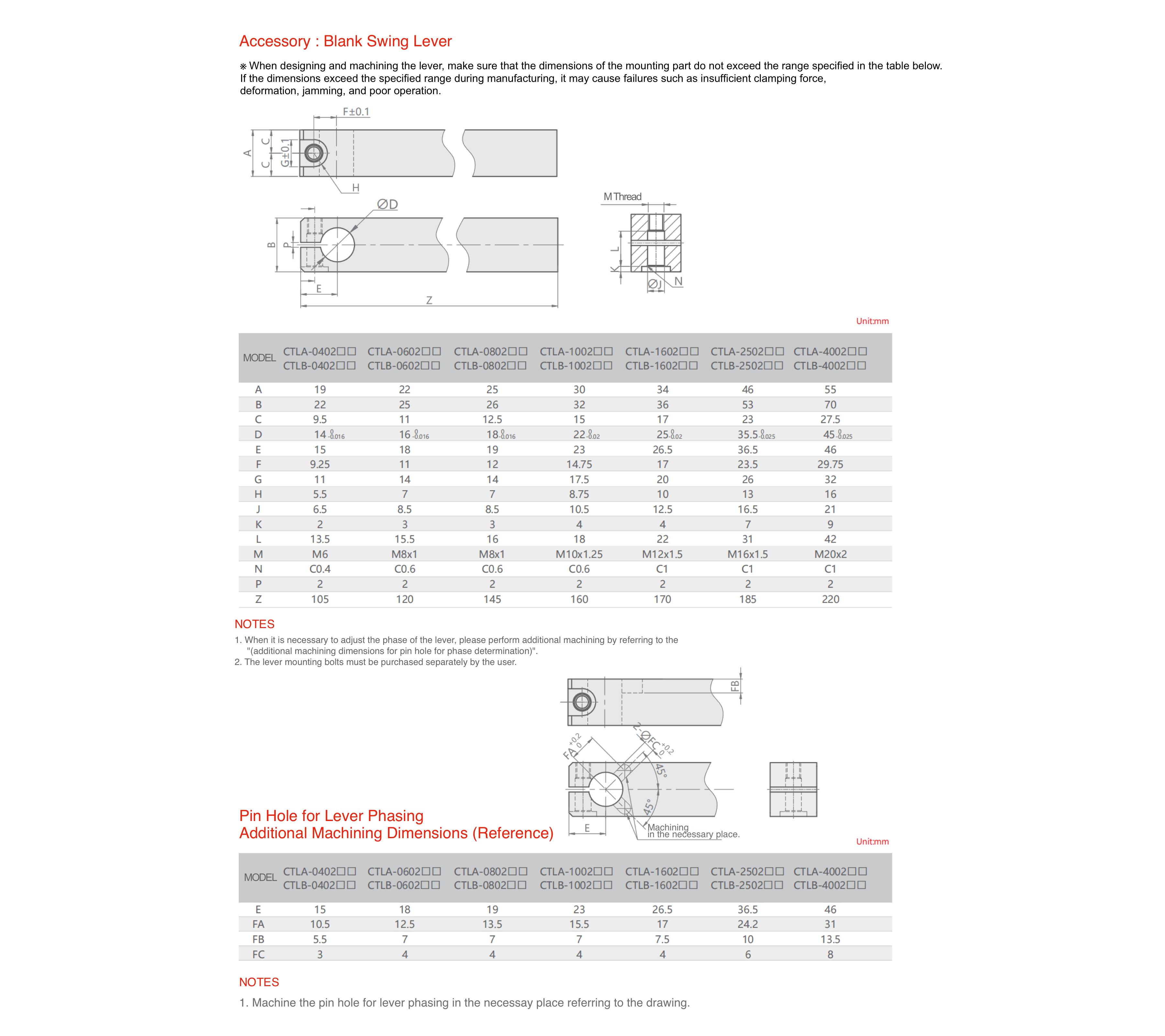
Clamping Arm Machining – Adjustment of Lever Position
If required, the clamping arm can be machined according to the dimensions shown below to adjust the lever position.
Note: The required fastening screws for the clamping arm must be sourced separately by the user.
CTLB Hydraulic High-Pressure Swing Clamp – CAD Data
CAD data is available for all sizes in STEP format for download.
Other versions and customized solutions are available on request.